LCD驱动程序编写
学习目标:编写LCD驱动程序,熟悉根据芯片手册分析时序图,配置寄存器,并测试LCD程序。
一、LCD驱动程序编写
步骤:
1)分配fb_info结构体
2)设置fb_info结构体
a. 固定参数
b. 可变参数
c. 操作函数
--设置调色板
d. fb_info的其它成员
--设置显存
3)硬件相关的操作
--配置GPIO用于用于LCD
--根据手册设置LCD控制器寄存器
--分配显存,并把地址告诉LCD控制器
4) 注册fb_info结构体
二、源码:
#include <linux/module.h>
#include <linux/kernel.h>
#include <linux/errno.h>
#include <linux/string.h>
#include <linux/mm.h>
#include <linux/slab.h>
#include <linux/delay.h>
#include <linux/fb.h>
#include <linux/init.h>
#include <linux/dma-mapping.h>
#include <linux/interrupt.h>
#include <linux/workqueue.h>
#include <linux/wait.h>
#include <linux/platform_device.h>
#include <linux/clk.h>
#include <asm/io.h>
#include <asm/uaccess.h>
#include <asm/div64.h>
#include <asm/mach/map.h>
#include <asm/arch/regs-lcd.h>
#include <asm/arch/regs-gpio.h>
#include <asm/arch/fb.h> //调色板
static int s3c_lcdfb_setcolreg(unsigned int regno, unsigned int red,
unsigned int green, unsigned int blue,
unsigned int transp, struct fb_info *info); //lcd寄存器
struct lcd_regs {
unsigned long lcdcon1;
unsigned long lcdcon2;
unsigned long lcdcon3;
unsigned long lcdcon4;
unsigned long lcdcon5;
unsigned long lcdsaddr1;
unsigned long lcdsaddr2;
unsigned long lcdsaddr3;
unsigned long redlut;
unsigned long greenlut;
unsigned long bluelut;
unsigned long reserved[];
unsigned long dithmode;
unsigned long tpal;
unsigned long lcdintpnd;
unsigned long lcdsrcpnd;
unsigned long lcdintmsk;
unsigned long lpcsel;
}; static struct fb_ops s3c_lcdfb_ops = {
.owner = THIS_MODULE,
.fb_setcolreg = s3c_lcdfb_setcolreg, //设置调色板
.fb_fillrect = cfb_fillrect,
.fb_copyarea = cfb_copyarea,
.fb_imageblit = cfb_imageblit,
}; static struct fb_info *s3c_lcd;
static volatile unsigned long *gpbcon;
static volatile unsigned long *gpbdat;
static volatile unsigned long *gpccon;
static volatile unsigned long *gpdcon;
static volatile unsigned long *gpgcon;
static volatile struct lcd_regs* lcd_regs;
static u32 pseudo_palette[]; /* from pxafb.c */
static inline unsigned int chan_to_field(unsigned int chan, struct fb_bitfield *bf)
{
chan &= 0xffff;
chan >>= - bf->length;
return chan << bf->offset;
} //设置调色板,供内核使用
static int s3c_lcdfb_setcolreg(unsigned int regno, unsigned int red,
unsigned int green, unsigned int blue,
unsigned int transp, struct fb_info *info)
{
unsigned int val; if (regno > )
return ; /* 用red,green,blue三原色构造出val,根据info结构体中设置的偏移,val最终是16位象素 */
val = chan_to_field(red, &info->var.red);
val |= chan_to_field(green, &info->var.green);
val |= chan_to_field(blue, &info->var.blue); //((u32 *)(info->pseudo_palette))[regno] = val;
pseudo_palette[regno] = val; //val放到调色板数组中
return ;
} static int lcd_init(void)
{
/* 1. 分配一个fb_info */
s3c_lcd = framebuffer_alloc(, NULL); /* 2. 设置 */
/* 2.1 设置固定的参数 */
strcpy(s3c_lcd->fix.id, "mylcd");
s3c_lcd->fix.smem_len = **/; //显存的长度=分辨率*每象素字节数 每个像素用16位表示(5:6:5);
s3c_lcd->fix.type = FB_TYPE_PACKED_PIXELS; //默认
s3c_lcd->fix.visual = FB_VISUAL_TRUECOLOR; /* TFT 真彩色*/
s3c_lcd->fix.line_length = *; //每行的长度,以字节为单位 /* 2.2 设置可变的参数 */
s3c_lcd->var.xres = ;
s3c_lcd->var.yres = ;
s3c_lcd->var.xres_virtual = ;
s3c_lcd->var.yres_virtual = ;
s3c_lcd->var.bits_per_pixel = ; //每个象素使用多少位 16bit /* RGB:565 */
s3c_lcd->var.red.offset = ;
s3c_lcd->var.red.length = ; s3c_lcd->var.green.offset = ;
s3c_lcd->var.green.length = ; s3c_lcd->var.blue.offset = ;
s3c_lcd->var.blue.length = ; s3c_lcd->var.activate = FB_ACTIVATE_NOW;//使设置的值立即生效 /* 2.3 设置操作函数 */
s3c_lcd->fbops = &s3c_lcdfb_ops; /* 2.4 其他的设置 */
s3c_lcd->pseudo_palette = pseudo_palette;//存放调色板所调颜色的数组
//s3c_lcd->screen_base = ; /* 显存的虚拟地址 */
s3c_lcd->screen_size = **/;//显存的大小 /* 3. 硬件相关的操作 */
/* 3.1 配置GPIO用于LCD */
gpbcon = ioremap(0x56000010, );
gpbdat = gpbcon+;
gpccon = ioremap(0x56000020, );
gpdcon = ioremap(0x56000030, );
gpgcon = ioremap(0x56000060, ); *gpccon = 0xaaaaaaaa; /* GPIO管脚用于VD[7:0],LCDVF[2:0],VM,VFRAME,VLINE,VCLK,LEND */
*gpdcon = 0xaaaaaaaa; /* GPIO管脚用于VD[23:8] */ *gpbcon &= ~(); /* GPB0设置为输出引脚 */
*gpbcon |= ;
*gpbdat &= ~; /* 输出低电平,关闭背光* */ *gpgcon |= (<<); /* GPG4用作LCD_PWREN信号*/ /* 3.2 根据LCD手册设置LCD控制器, 比如VCLK的频率等 */
lcd_regs = ioremap(0x4D000000, sizeof(struct lcd_regs)); /* bit[17:8]: VCLK = HCLK / [(CLKVAL+1) x 2], LCD手册P14
* 10MHz(100ns) = 100MHz / [(CLKVAL+1) x 2]
* CLKVAL = 4
* bit[6:5]: 0b11, TFT LCD
* bit[4:1]: 0b1100, 16 bpp for TFT
* bit[0] : 0 = Disable the video output and the LCD control signal.
*/
lcd_regs->lcdcon1 = (<<) | (<<) | (0x0c<<); #if 1
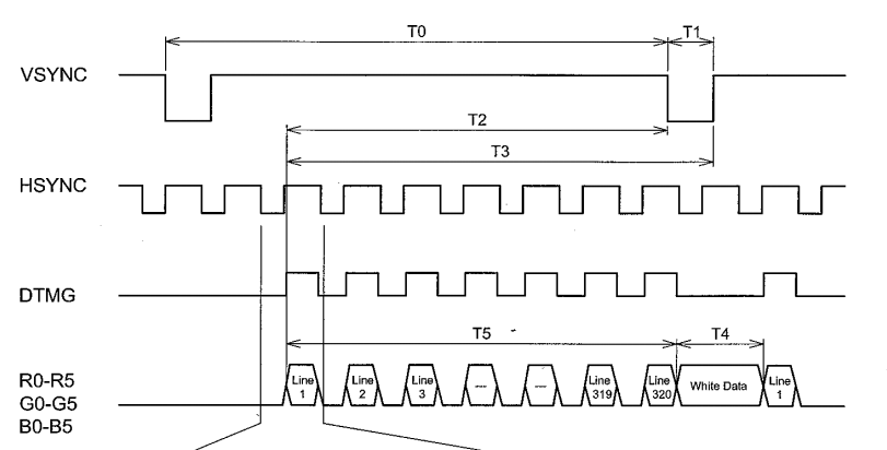
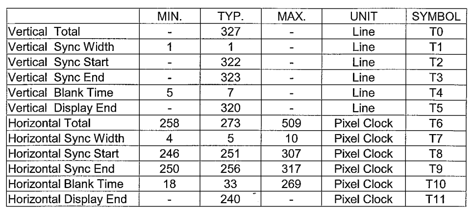
/* 垂直方向的时间参数
* bit[31:24]: VBPD, VSYNC之后再过多长时间才能发出第1行数据
* LCD手册 T0-T2-T1=4
* VBPD=3
* bit[23:14]: 多少行, 320, 所以LINEVAL=320-1=319
* bit[13:6] : VFPD, 发出最后一行数据之后,再过多长时间才发出VSYNC
* LCD手册T2-T5=322-320=2, 所以VFPD=2-1=1
* bit[5:0] : VSPW, VSYNC信号的脉冲宽度, LCD手册T1=1, 所以VSPW=1-1=0
*/
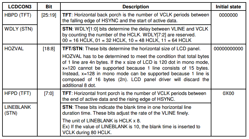
lcd_regs->lcdcon2 = (<<) | (<<) | (<<) | (<<); /* 水平方向的时间参数
* bit[25:19]: HBPD, VSYNC之后再过多长时间才能发出第1行数据
* LCD手册 T6-T7-T8=17
* HBPD=16
* bit[18:8]: 多少列, 240, 所以HOZVAL=240-1=239
* bit[7:0] : HFPD, 发出最后一行里最后一个象素数据之后,再过多长时间才发出HSYNC
* LCD手册T8-T11=251-240=11, 所以HFPD=11-1=10
*/
lcd_regs->lcdcon3 = (<<) | (<<) | (<<); /* 水平方向的同步信号
* bit[7:0] : HSPW, HSYNC信号的脉冲宽度, LCD手册T7=5, 所以HSPW=5-1=4
*/
lcd_regs->lcdcon4 = ;
//lcd寄存器配置的另一种写法
#else
lcd_regs->lcdcon2 = S3C2410_LCDCON2_VBPD() | \
S3C2410_LCDCON2_LINEVAL() | \
S3C2410_LCDCON2_VFPD() | \
S3C2410_LCDCON2_VSPW(); lcd_regs->lcdcon3 = S3C2410_LCDCON3_HBPD() | \
S3C2410_LCDCON3_HOZVAL() | \
S3C2410_LCDCON3_HFPD(); lcd_regs->lcdcon4 = S3C2410_LCDCON4_MVAL() | \
S3C2410_LCDCON4_HSPW(); #endif
/* 信号的极性
* bit[11]: 1=565 format
* bit[10]: 0 = The video data is fetched at VCLK falling edge
* bit[9] : 1 = HSYNC信号要反转,即低电平有效
* bit[8] : 1 = VSYNC信号要反转,即低电平有效
* bit[6] : 0 = VDEN不用反转
* bit[3] : 0 = PWREN输出0
* bit[1] : 0 = BSWP
* bit[0] : 1 = HWSWP 2440手册P413
*/
lcd_regs->lcdcon5 = (<<) | (<<) | (<<) | (<<) | (<<); /* 3.3 分配显存(framebuffer), 并把地址告诉LCD控制器 */
s3c_lcd->screen_base = dma_alloc_writecombine(NULL, s3c_lcd->fix.smem_len, &s3c_lcd->fix.smem_start, GFP_KERNEL); lcd_regs->lcdsaddr1 = (s3c_lcd->fix.smem_start >> ) & ~(<<); //对应内存起始地址的 A[30:1] ,则起始地址右移1位,&0x3fffffff 共30位
lcd_regs->lcdsaddr2 = ((s3c_lcd->fix.smem_start + s3c_lcd->fix.smem_len) >> ) & 0x1fffff;
lcd_regs->lcdsaddr3 = (*/); /* 一行的长度(单位: 2字节) */ //s3c_lcd->fix.smem_start = xxx; /* 显存的物理地址 */
/* 启动LCD */
lcd_regs->lcdcon1 |= (<<); /* 使能LCD控制器 */
lcd_regs->lcdcon5 |= (<<); /* 使能LCD本身 */
*gpbdat |= ; /* 输出高电平, 使能背光 */ /* 4. 注册 */
register_framebuffer(s3c_lcd);
return ;
}
static void lcd_exit(void)
{
unregister_framebuffer(s3c_lcd);
lcd_regs->lcdcon1 &= ~(<<); /* 关闭LCD本身 */
*gpbdat &= ~; /* 关闭背光 */
dma_free_writecombine(NULL, s3c_lcd->fix.smem_len, s3c_lcd->screen_base, s3c_lcd->fix.smem_start);//3为虚拟地址
iounmap(lcd_regs);
iounmap(gpbcon);
iounmap(gpccon);
iounmap(gpdcon);
iounmap(gpgcon);
framebuffer_release(s3c_lcd);
}
module_init(lcd_init);
module_exit(lcd_exit);
MODULE_LICENSE("GPL");
LCD寄存器配置分析:
1、lcdcon1 寄存器配置
  /* bit[17:8]: VCLK = HCLK / [(CLKVAL+1) x 2], LCD手册P14

   *            10MHz(100ns) = 100MHz / [(CLKVAL+1) x 2]

   *            CLKVAL = 4

   * bit[6:5]: 0b11, TFT LCD

   * bit[4:1]: 0b1100, 16 bpp for TFT

   * bit[0]  : 0 = Disable the video output and the LCD control signal.

   */

  lcd_regs->lcdcon1  = (<<) | (<<) | (0x0c<<);
查看2440说明书,找到lcdcon1 寄存器,确定每一位的取值:
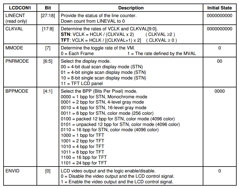
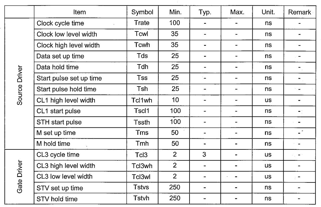
1)bit[17:8] VCLK = HCLK / [(CLKVAL+1) x 2]计算CLKVAL的值,首先使用# dmesg命令查看内核打印信息,获取HCLK为100MHz。
查看液晶屏的芯片手册Clock cycle time 可知:VCLK = 100ns ==> 10MHz,从而可知 10=100/[(CLKVAL+1) x 2]==> CLKVAL=4 bit[17:8]就是4;
2)bit[6:5]: 0b11, TFT LCD;
3)bit[0] : 0 LCD信号输出使能位禁止。
2、lcdcon2
    /* 垂直方向的时间参数

       * bit[31:24]: VBPD, VSYNC之后再过多长时间才能发出第1行数据

       *             LCD手册 T0-T2-T1=4

       *             VBPD=3

       * bit[23:14]: 多少行, 320, 所以LINEVAL=320-1=319

       * bit[13:6] : VFPD, 发出最后一行数据之后,再过多长时间才发出VSYNC

       *             LCD手册T2-T5=322-320=2, 所以VFPD=2-1=1

       * bit[5:0]  : VSPW, VSYNC信号的脉冲宽度, LCD手册T1=1, 所以VSPW=1-1=0

 */

      lcd_regs->lcdcon2  = (<<) | (<<) | (<<) | (<<);
lcdcon2 寄存器,确定每一位的取值:
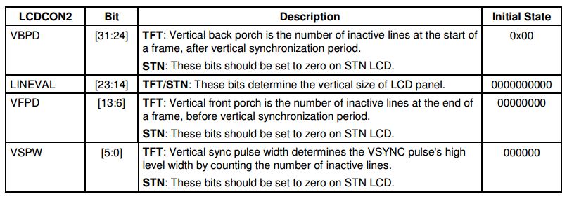
1) * bit[31:24]: 垂直方向的时间参数 VBPD, 即VSYNC之后再过多长时间才能发出第1行数据。
查看2440 LCD控制器的手册:
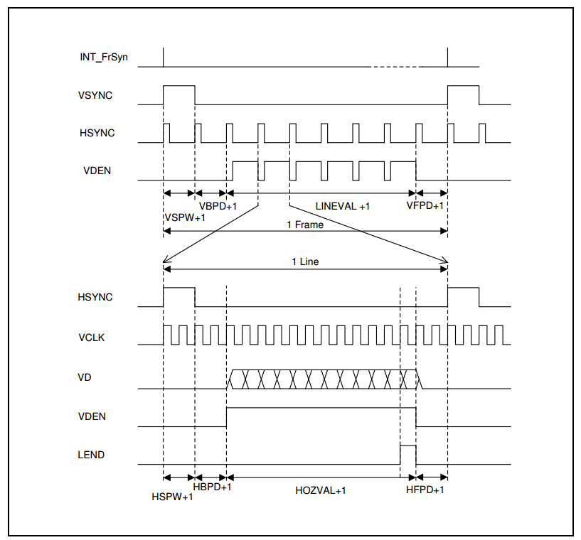
由上图可知:
VFPD+1=T2-T5=322-320, VFPD=1
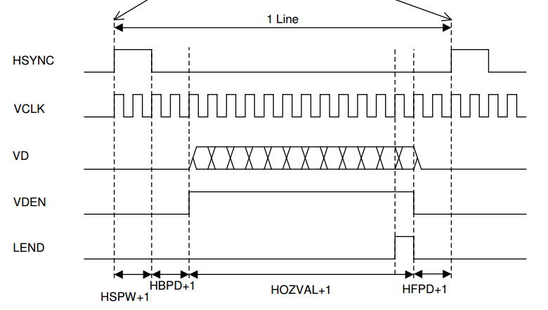

2) bit[18:8]: 多少列, 240, 所以HOZVAL=240-1=239
3) bit[7:0] : HFPD, 发出最后一行里最后一个象素数据之后,再过多长时间才发出HSYNC
HFPD+1=T8-T11=251-240=11, 所以HFPD=10
4、lcdcon4
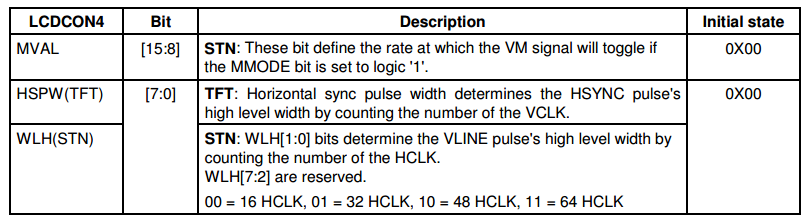
* bit[7:0] : HSPW, HSYNC信号的脉冲宽度,HSPW+1=T7,HSPW=4
*/
三、编译测试
第一种方法:
1) make menuconfig去掉原来的驱动程序
-->Device Drivers
-->Graphics support
<M>S3C2410 LCD framebuffer support
2) 编译内核和模块
# make uImage
# make modules //把用到的程序编译成模块运行
3)编译lcd驱动为模块,将生成的lcd.ko和driver/video目录下用到的cfbcopyarea.ko、cfbfillrect.ko、 cfbimgblt.ko (lcd驱动程序中的fb_ops会用到)拷贝到/work/nfs_root/first_fs/lcd_test目录下。
4) 烧写uImage并启动开发板,并加载模块:
# nfs 30000000 10.70.12.103:/work/nfs_root/uImage_nolcd
# insmod cfbcopyarea.ko
# insmod cfbfillrect.ko
# insmod cfbimgblt.ko
# insmod lcd.ko
使用# ls /dev/fb* ,可以看到设备节点:/dev/fb0.
5) echo hello > /dev/tty1 // 可以在LCD上看见hello
cat lcd.ko > /dev/fb0 // 花屏
第二种测试方法:
1)修改/etc/inittab (添加:tty1::askfirst:-/bin/sh) 输出到tty1(对应为显示屏)//将/bin/sh信息输出到tty1中;
类似于:s3c2410_serial0::askfirst:-/bin/sh 输出到串口。
用新内核重启开发板
insmod cfbcopyarea.ko
insmod cfbfillrect.ko
insmod cfbimgblt.ko
insmod lcd.ko
insmod buttons.ko
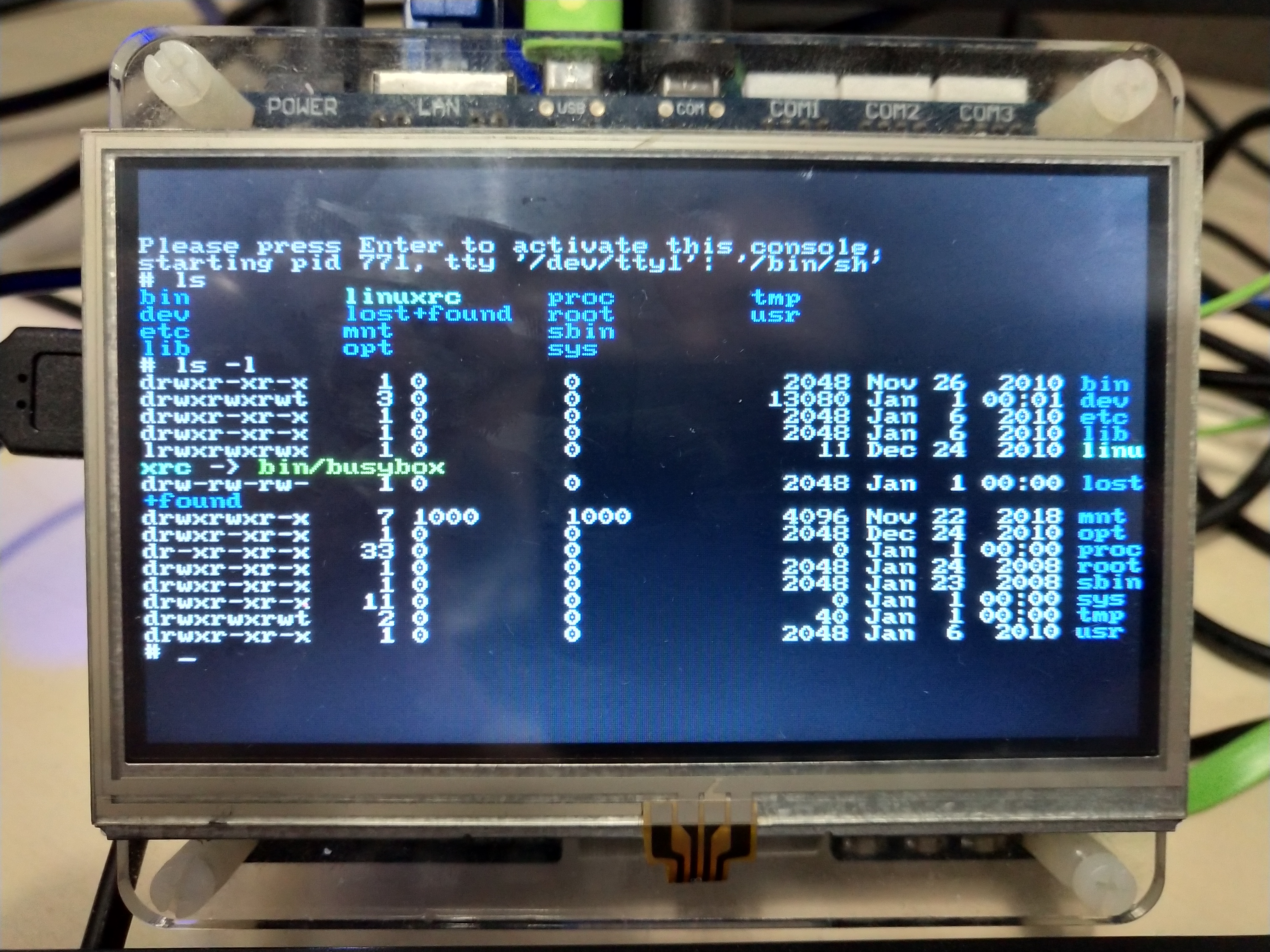
可以看到Please。。。。。。。。。等一行字符
接着,将以前的USB键盘驱动,加载:# insmod ../usb_keyboard.ko
插上键盘后,可以在LCD显示终端控制信息:
最新文章
- JAVA-系统-【2】-创建自增长的用户表
- sehll_if
- new char[]和new char()的区别
- 03-树2 Tree Traversals Again
- [C语言 - 1.2] 类型说明符、字符、数组
- Spring 的@Controller 和@RestController的区别
- [状压dp]HDOJ4539 郑厂长系列故事——排兵布阵
- ios页面跳转
- 使用netty的第一个Hello World
- 使用Perfect Player观看电视直播
- js java 给定一个目标值,在一棵树中找是否有两个节点的值之和等于目标值
- LoadRunner之IP欺骗
- java.lang.ClassNotFoundException但是项目里明明已经存在
- VSC 插件开发从入门到Hello World
- 添加信任站点和允许ActiveX批处理
- 【redis运维】redis自己主动安装脚本(仅仅安装redis)
- 文件上传及时显示, 前端js和后端php相互结合使用
- python之csv操作问题
- Android4.4 SystemUI加入Dialog弹窗
- Java各类格式转换