Rendering in UE4
Intro
Thinking performance.
Identify the target framerate, aim your approach on hitting that target framerate.
- Everything needs to be as efficient as possible
- Adjust pipelines to engine and hardware restrictions
- Try to offload parts to pre-calculations
- Use the engine’s pool of techniques to achieve quality at suitable cost
What is rendering?
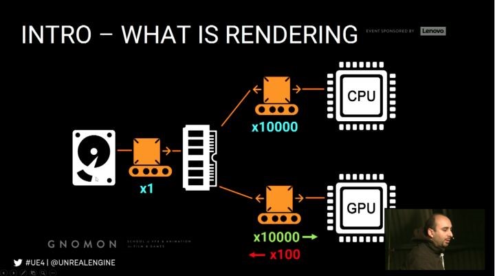
- CPU and GPU handle different parts of the rendering calculations
- They are interdependent and can bottleneck each other
- Know how to the load is distributed between the 2
Shading Techniques
- Deferred shading
- Compositing based using the G-Buffer
- Shading happens in deferred passes
- Good at rendering dynamic lighting
- More flexible when it comes to disabling features, less flexible when it comes to surface attributes
- Forward shading
Before Rendering
Rendering threads
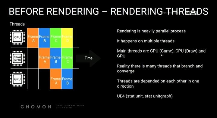
Rendering is heavily parallel process. It happens on multiple threads, main threads are CPU(Game), CPU(Draw) and
GPU, reality there is many threads that branch and converge.
UE4 Cmd (stat unit, stat unitgraph)
CPU – Game thread
Before we can render anything we first need to know where everything will be,
Calculate all logic and transforms
- Animations
- Positions of models and objects
- Physics
- AI
- Spawn and destroy, hide and unhide
Results: UE4 now knows all transforms of all models.
CPU – Draw thread
Before we can use the transforms to render the image we need to know what to include in the rendering, ignoring this
question might take rendering expensive on GPU.
Occlusion process – Builds up a list of all visible models/objects, happens per object – not per triangle
4 Stage process
- Distance Culling (manually, LOD Component, Cull Distance Volume)
- Frustum Culling (what is in front of the camera, wide FOV more objects to render)
- Precomputed Visibility
- Occlusion Culling
Precomputed visibility answers more complex occlusion questions,
Objects occluded by other objects, divides the scene into a grid, each grid cell remembers what is visible at that location.
Dynamic Occlusion Culling checks the visibility state on every model, that is mostly run on the CPU but some parts are
GPU handled.
Occlusion Performance Implication
- Set up manual culling (i.e. distance culling, per-computed vis)
- Even things like particles occlude
- Many small objects cause more stress on CPU for culling
- Large models will rarely occlude and thus increase GPU
- Know your world and balance objects size vs count

Results: UE4 now has a list of models to render.
Geometry Rendering
The GPU now has a list of models and transforms but if we just render this info out we could possibly cause a lot of
redundant pixel rendering. Similar to excluding objects, we need to exclude pixels, we need to figure out which pixels
are occluded.
To do this, we generate a depth pass and use it to determine if the given pixel is in front and visible.
GPU – Prepass / Early-Z Pass
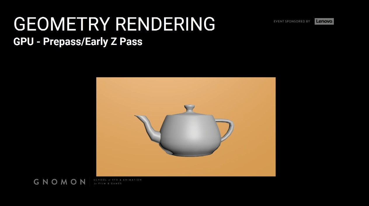
Render teapot first, then render the box.

Previous strategy doesn’t work, that why we need to depend on the depth of those pixels to know if this object or this
pixel is behind in front of another object and then decide if we need to render it.
Question 1. How does the renderer associate the early-z pass with an actual object in the scene?
It doesn’t really associated object per object what it happens, it knows the position of pixel on the screen, so what it
need to render an object or a pixel it knows. Ignore it or keep it.
Draw calls
- Now we are ready to actually rendering some geometries, so in order to be efficient, the GPU render a drawcall by
drawcall, not a triangle by a triangle. - A drawcall is it’s a group of triangles that share the same properties.
- Drawcalls are prepared by CPU(Draw) thread
- Distilling rendering info for objects into a GPU state ready for submission
2,000 – 3,000 is reasonable, more than 5,000 is getting high, more than 10,000 is probably a problem, on mobile this number
is far lower (few hundred max), draw calls is determined by visible objects.
- Drawcalls have a huge impact on the CPU (draw) thread
- Has high overhead for preparing GPU states
- Usually we hit the issues with drawcalls way before issues with tri count.
Imagination of the overhead of a draw call vs that triangles,
Copying 1 single 1GB file vs Copying 1 million 1KB files.
Drawcalls performance implications:
- Render your triangles with as few drawcalls as possible
- 50,000 triangles can run worse than 50 million dependents on scene setup (Drawcalls)
- When optimizing scene, know your bottleneck (Drawcall vs Tri count)
Optimizing Drawcalls
Merging objects
To lower the drawcalls it is better to use fewer larger models than many small ones. You can do that too much, it impacts
other things negatively
- Occlusion
- Lightmapping
- Collision calculation
- Memory
Good balance between size and count is a good strategy.
Drawcall is related directly to how many objects you have and how many unique material IDs you have.
Merging guidelines
- Target low poly objects
- Merge only meshes within the same area
- Merge only meshes sharing the same material
- Meshes with no or simple collision are better for merging
- Distant geometry is usually great to merge (fine with culling)
HLODs
Hierarchical Level of Detail
- Regular LODs means a model becomes lower poly in the distance
- Essentially swaps one object for another simpler object (less materials)
- Hierarchical LOD (HLOD) is a bigger version, it merges objects together in the distance to lower the drawcalls
- Groups objects together into single drawcalls
- Grouping need to be done manually
Instanced Rendering
- Groups objects together into single drawcalls
- Grouping need to be done manually
Vertex Processing
First thing processing the Drawcall
Vertex shader takes care of this process
Vertex shader is a small program specialized in vertex processing
Runs completely on the GPU and so they are fast
Input is vertex data in 3D space output vertex data in screen-space
Vertex shaders – Common tasks
- It converts local VTX positions to world position
- It handles vertex shading/coloring
- It can apply additional offsets to vertex positions
Practical examples of world position offset vertex shaders are
- Cloth
- Water displacement
- Foliage wind animation
Why animate things this way?
Scalability with very high number of vertices, imagine a forest, it could involve millions of vertices to animate.
Vertex shaders do not modify the actual object or affect the scene state, it is purely a visual effect.
The CPU is not aware of what the vertex shaders do, thus things like physics or collisions will not take it into account.
Vertex Shaders Performance Implications
- The more complex the animations performed the slower
- The more vertices affected the slower
- Disable complex vertex shader effects on distant geometry
Rasterizing and G-Buffer
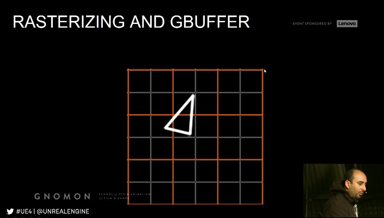
Rasterizing
GPU ready to render pixels, determine which pixels should be shaded called rasterizing, done drawcall by drawcall,
then tri by tri.
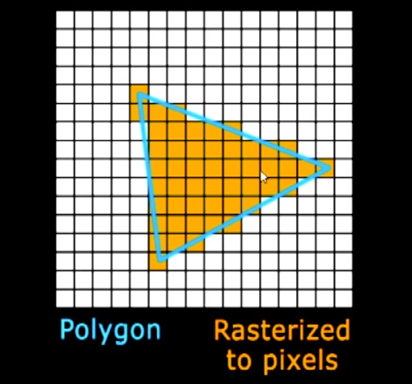
See here on this magnified pixel grid, we have a blue triangle and the rasterization for this triangle gives up those
orange pixels. Now the thing that need to know it happens drawcall by drawcall again to be more efficient, then it
goes triangle by triangle by same order it is submitted to the GPU.
Pixel shaders are responsible for calculating the pixel color, input is generally interpolated vertex data, texture
samplers, … etc.
Rasterizing inefficiency
When rasterizing dense meshes at distance, they converge to only few pixels. A waste of vertex processing.
i.e. A 100k tris object seen from so far away that it would be 1 pixel big, will only show 1 pixel of its closest triangle!
Overshading
Due to hardware design, it always uses a 2x2 pixel quad for processing. If a triangle is very small or very thin then
it means it might process 4 pixels while only 1 pixel is actually filled.
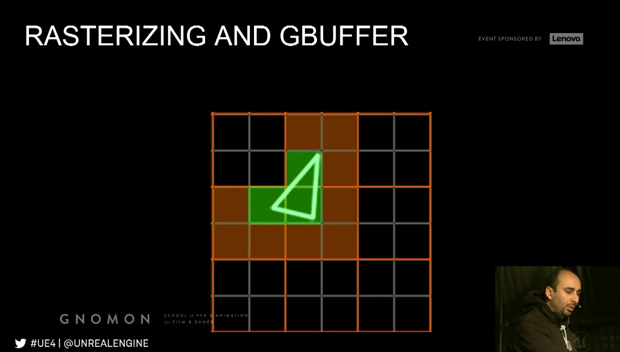
The gray gird is basically pixels, and the orange grid on the top which is the pixel quads that the GPU can process.
So, if we have a tiny triangle like first pic, ideally, we only having three pixels so we just need to process through those
three pixels to output the final color. However, in reality this is not what happens on the GPU, the GPU need to process
12 pixels just to render us those three pixels at the end. So, here we see like our first waste of pixel processing for small
triangles.
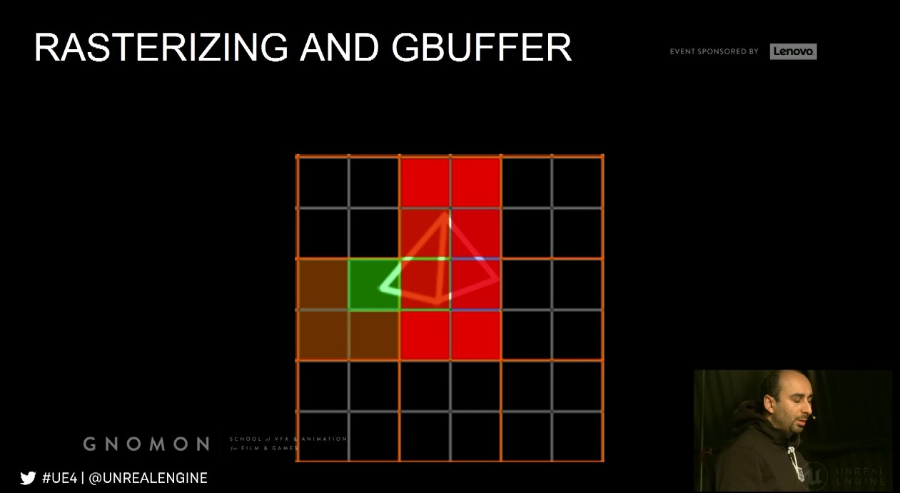
Even worse case,

How to visualize overshading, Lit -> Optimization View modes -> Quad Overdraw.
Rasterization and Overshading Performance Implications
- Triangles are more expensive to render in great density
- When seen at a distance the density increases
- Thus, reducing triangle count at a distance (lodding / culling) is critical
- Very thin triangles are inefficient because they pass through many 2x2 pixel quads yet only fill a fraction of them
- The more complex the pixel shader is the more expensive overshading
Result are written out to:
- Multiple G-Buffers in case of deferred shading
- Shaded buffer in case of forward shading
G-Buffer
It is a rendered image encoding special data, these buffers are then used for different uses – mainly lighting, the frame
rendered out in multiple G-Buffers.
Custom Depth allows for rendering out an additional mask, which in turn can used for Chroma keying.
G-Buffer Performance Implications
The G-Buffer takes a lot of memory and bandwidth and thus has a limit on how many different G-Buffer images you can render out.
G-Buffer’s memory is resolutions dependent.
Dynamic Lighting/Shadows
Two approaches for lighting and shadows, dynamic and static.
UE4 separate between lighting and shadow data calculated in real time, so it allows for dynamic lights and dynamic objects
to considered, has another light type of lighting and shadow, which is very specific to static or pre-calculating lighting and shadows.
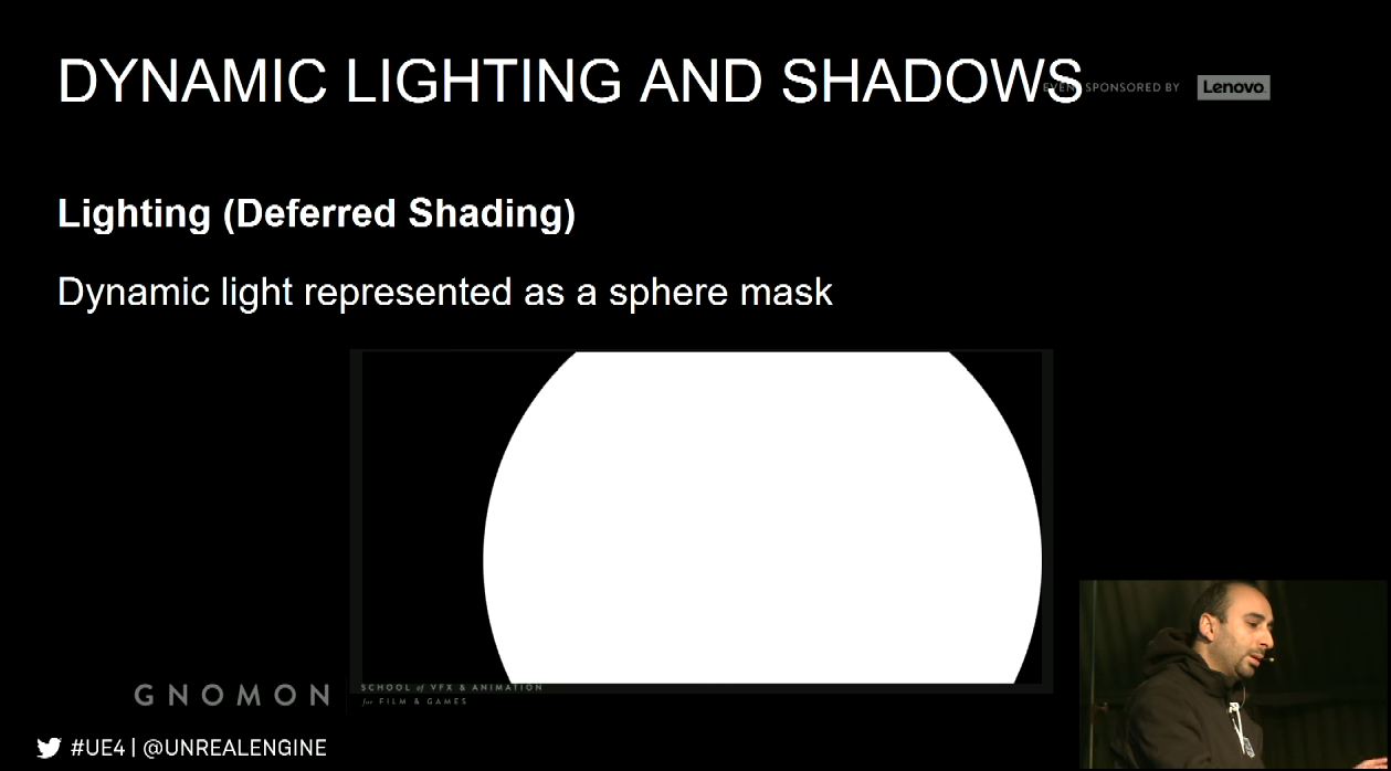
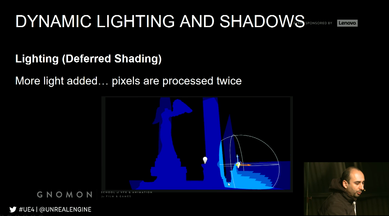
Lighting (Deferred Shading)
- Lighting is calculated and applied using pixel shaders
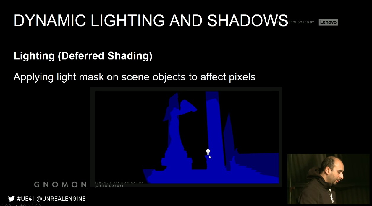
- Dynamic point lights are rendered as spheres
- The spheres act like a mask
- Anything within the sphere is to receive a pixel shader operation to blend in the dynamic light
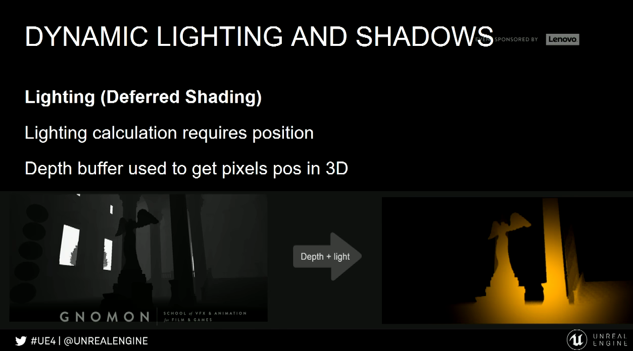
Light attributes (e.g. color, falloff, intensity … etc.) considered in pixel shader.
Lighting calculation requires position. Depth buffer used to get pixels position in 3D.
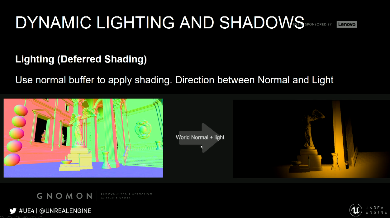
Use normal buffer to apply shading. Direction between normal and light.
Shadows
Common techniques for rendering shadows is Shadow Maps, and concept behind shadow maps is checking for each
pixel if it is visible to the given light or not. In order to do this we need to render a depth pass, but now instead of
having it from the camera point of view we need to render it from the light point of view.
Generate a depth pass from the light point of view, and able to do this we need to go back and go through the rendering
process beginning, so we need to project them, we need to calculate many things so all the optimization and the processing
we gone through for rendering the main passes. As if we are almost rendering the scene twice, just to calculate the shadows.
Process Pros/Cons
- Pros
- Is rendered in real time using the G-Buffer
- Lights can be changed, moved, or added/removed at all
- Does not need any special model preparation
- Cons
- Especially shadows are performance heavy
Quality Pros/Cons
- Shadows are heavy on performance, so usually render quality is reduced to compensate
- Does not do radiosity/global illumination for majority of content
- Dynamic soft shadows are very hard to do well, dynamic shadows often looks sharp or blocky
Dynamic Lighting Performance Implications
- Small dynamic light is relatively cheap in a deferred renderer
- The cost is down to pixel shader operations, so the more pixels the slower it is
- The radius must be as small as possible
- Prevent excessive and regular overlap
In UE4,
- Turn off shadow casting if not needed
- The triangle count of geometry affects shadows performance
- Fade or toggle off shadows when far away
Static Lighting/Shadows
Dynamic lights and shadows are expensive, thus part of it offloaded to pre-calculations / pre-rendering. This referred as
static lights and shadows.
Lighting data stored mainly in Lightmaps.
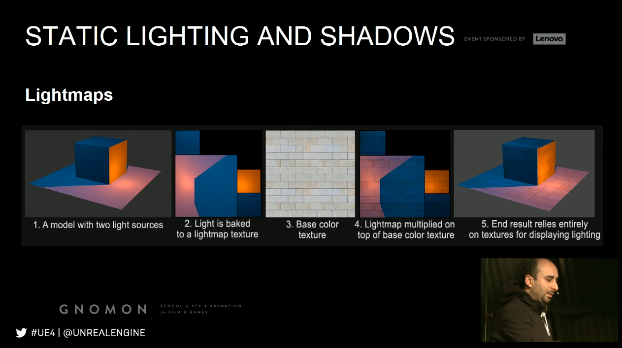
Lightmaps
A Lightmap is a texture with the lighting and shadows baked into it.
An object usually requires UV Lightmap coordinates for this to work; this texture then multiplied on top of the basecolor.
Working out lightmaps manually for large scenes is not scalable; lightmaps generated by UE4 using lightmass.
Lightmass
- Standalone application that handles light rendering, baking to lightmaps and integrating into materials
- Ray tracer supporting GI
- Supports distributed rendering over a network
- Light Build Quality as well as settings in the Lightmass section of each level determine bake quality
- Better to have a Lightmass Importance Volume around parts of the world
Process Pros/Cons
- Super fast for performance in real-time, but increases memory
- Takes a long time to pre-calculate lighting
- Each time something is changed, it must be re-rendered again
- Models require lightmap UVs, this additional prep step that takes time
- Handles radiosity and Global illumination
- Renders realistic shadows including soft shadows
- Quality is dependent on lightmap resolution and UV layout
- Maya have seams in the lighting due to the UV layout
- Static Lighting always renders at the same speed
- Lightmap resolution affects memory and file size, not framerate
- Bake times are increased by
Quality Pros/Cons
Static Lighting Performance Implications
a) Lightmap resolutions
b) Number of models/lights
c) Higher quality settings
d) Lights with a large attenuation radius or source radius
Lighting and Shadows
Mixing
Mixing static and dynamic is often (but not always) the best way to go
- Use static for weak and distant lighting
- Use static to render indirect lighting
- Use dynamic lighting on top of the static to better accentuate the shading and shadows and provide an
interactive layer on top of the static result
Post Processing
Visual effects applied at the very end of the rendering process
Using the G-Buffers to calculate its effects
Once more relies heavily on pixel shaders
Examples:
Light Bloom, Depth of Field/Blurring, Some types of lens flares, Light Shafts, Vignette, Tone Mapping, Color
correction, Exposure, Motion Blur.
Post Processing Performance Implications
- Affected directly by final resolution
- Affected by shader complexity
- Parameters
最新文章
- xamarin UWP证书问题汇总
- JSP连接mysql数据库的重点
- ***PHP中error_reporting()用法详解(含codeigniter框架中屏蔽错误提示的解决方案)
- UVA 11624 Fire!(广度优先搜索)
- simple_html_dom使用小结
- 制作标签(Label)
- RBAC角色权限控制
- linux中必会的目录
- UITableView的性能优化1
- 常用Windows DOS命令项目部署经常用到
- 网络流24题 ——运输问题 luogu 4015
- js 正则表达式的使用(标志 RegExp exec() test() compile() $1...$9)
- java 可设置最大内存
- .sh文件启动 jenkins
- Spring RPC 入门学习(2)-获取Map对象
- Golang的数组初始化方式及for-range遍历
- String类的知识点(不断更新)
- JavaScript事件-this传递
- [Deep-Learning-with-Python] Keras高级概念
- DDMS介绍