Linux0.11源码学习(二)
Linux0.11源码学习(二)
linux0.11源码学习笔记
参考资料:https://github.com/sunym1993/flash-linux0.11-talk
源码查看:https://elixir.bootlin.com/linux/latest/source
/boot/setup.s
entry start

start:

! ok, the read went well so we get current cursor position and save it for

! posterity.

	mov	ax,#INITSEG	! this is done in bootsect already, but...

	mov	ds,ax

	mov	ah,#0x03	! read cursor pos

	xor	bh,bh

	int	0x10		! save it in known place, con_init fetches

	mov	[0],dx		! it from 0x90000.
含义:
触发 BIOS 提供的显示服务中断处理程序,而 ah 寄存器被赋值为 0x03 表示显示服务里具体的读取光标位置功能。这个 int 0x10 中断程序执行完毕并返回时,dx 寄存器里的值表示光标的位置,具体说来其高八位 dh 存储了行号,低八位 dl 存储了列号。
ps:计算机在加电自检后会自动初始化到文字模式,在这种模式下,一屏幕可以显示 25 行,每行 80 个字符,也就是 80 列。
mov [0],dx 就是把这个光标位置存储在 [0] 这个内存地址处。最终的内存地址是在 0x90000 处,这里存放着光标的位置,以便之后在初始化控制台的时候用到。
! Get memory size (extended mem, kB) 获取内存信息。

	mov	ah,#0x88

	int	0x15

	mov	[2],ax

! Get video-card data:  获取显卡显示模式。

	mov	ah,#0x0f

	int	0x10

	mov	[4],bx		! bh = display page

	mov	[6],ax		! al = video mode, ah = window width

! check for EGA/VGA and some config parameters 检查显示方式并取参数

	mov	ah,#0x12

	mov	bl,#0x10

	int	0x10

	mov	[8],ax

	mov	[10],bx

	mov	[12],cx

! Get hd0 data  获取第一块硬盘的信息。

	mov	ax,#0x0000

	mov	ds,ax

	lds	si,[4*0x41]

	mov	ax,#INITSEG

	mov	es,ax

	mov	di,#0x0080

	mov	cx,#0x10

	rep

	movsb

! Get hd1 data  获取第二块硬盘的信息。

	mov	ax,#0x0000

	mov	ds,ax

	lds	si,[4*0x46]

	mov	ax,#INITSEG

	mov	es,ax

	mov	di,#0x0090

	mov	cx,#0x10

	rep

	movsb
含义:
程序方法与上述相同,就是调用一个 BIOS 中断获取点什么信息,然后存储在内存中某个位置。
上述程序我们能够知道被存到内存的信息是什么:
| 内存地址 | 长度(字节) | 名称 |
|---|---|---|
| 0x90000 | 2 | 光标位置 |
| 0x90002 | 2 | 扩展内存数 |
| 0x90004 | 2 | 显示页面 |
| 0x90006 | 1 | 显示模式 |
| 0x90007 | 1 | 字符列数 |
| 0x90008 | 2 | 未知 |
| 0x9000A | 1 | 显示内存 |
| 0x9000B | 1 | 显示状态 |
| 0x9000C | 2 | 显卡特性参数 |
| 0x9000E | 1 | 屏幕行数 |
| 0x9000F | 1 | 屏幕列数 |
| 0x90080 | 16 | 硬盘1参数表 |
| 0x90090 | 16 | 硬盘2参数表 |
| 0x900FC | 2 | 根设备号 |
这里的信息被约定好使用一个确定的内存地址,便于汇编语言和c语言同时编程。
! now we want to move to protected mode ...

	cli			! no interrupts allowed !
解释:
关闭中断。
因为后面我们要把原本是 BIOS 写好的中断向量表给覆盖掉,也就是给破坏掉了,写上我们自己的中断向量表,所以这个时候是不允许中断进来的。
! first we move the system to it's rightful place

	mov	ax,#0x0000

	cld			! 'direction'=0, movs moves forward

do_move:

	mov	es,ax		! destination segment

	add	ax,#0x1000

	cmp	ax,#0x9000

	jz	end_move

	mov	ds,ax		! source segment

	sub	di,di

	sub	si,si

	mov 	cx,#0x8000

	rep

	movsw

	jmp	do_move

! then we load the segment descriptors

end_move:
解释:
rep 表示重复执行后面的指令,这里表示重复执行movsw。
rep movsw 同前面的原理一样,也是做了个内存复制操作。最终的结果是,把内存地址 0x10000 处开始往后一直到 0x90000 的内容,统统复制到内存的最开始的 0 位置。
图解:
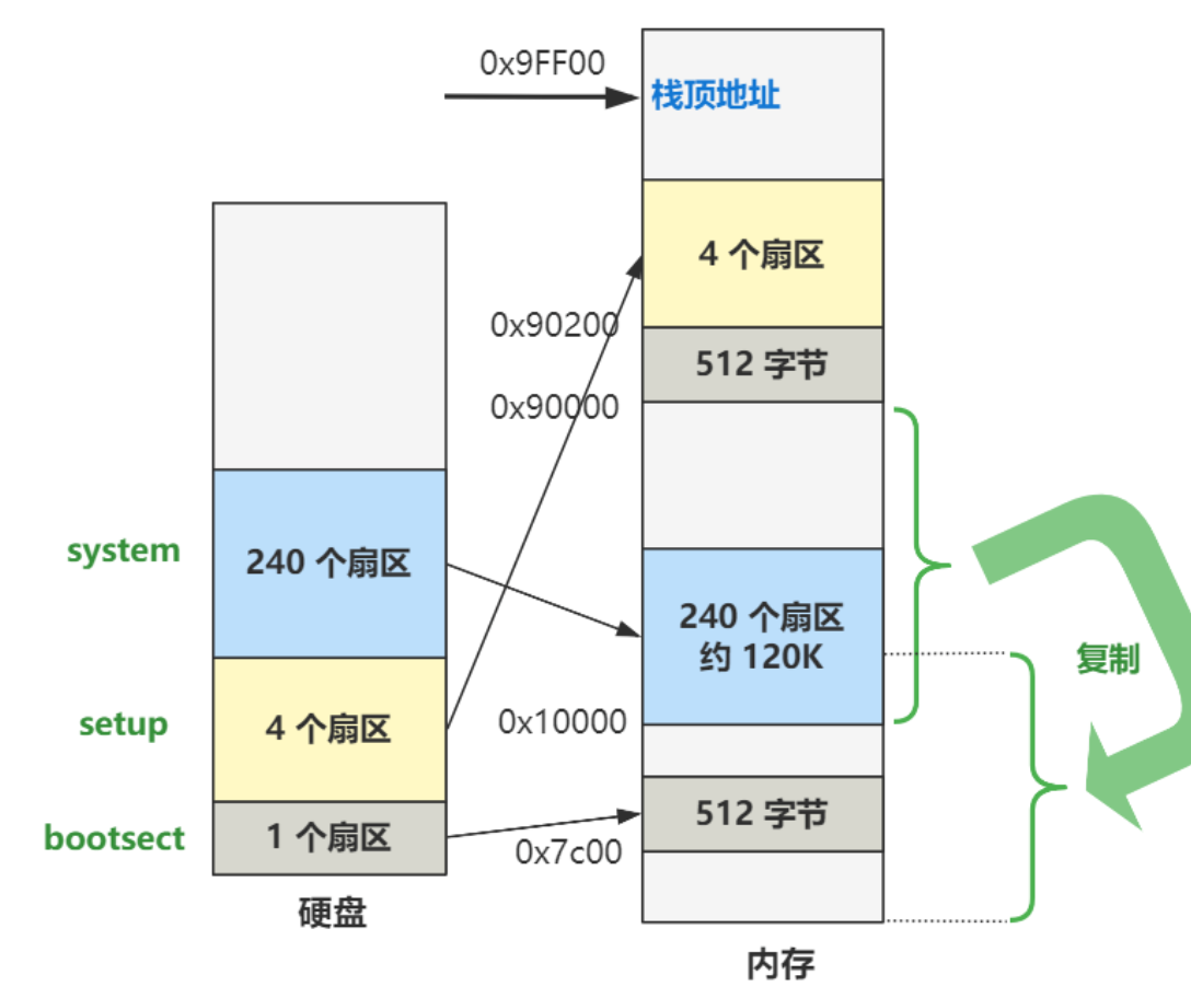
栈顶地址仍然是 0x9FF00 没有改变。
0x90000 开始往上的位置,原来是 bootsect 和 setup 程序的代码,现 bootsect 的一部分代码在已经被操作系统为了记录内存、硬盘、显卡等一些临时存放的数据给覆盖了一部分。
内存最开始的 0 到 0x80000 这 512K 被 system 模块给占用了,之前讲过,这个 system 模块就是除了 bootsect 和 setup 之外的全部程序链接在一起的结果,可以理解为操作系统的全部。
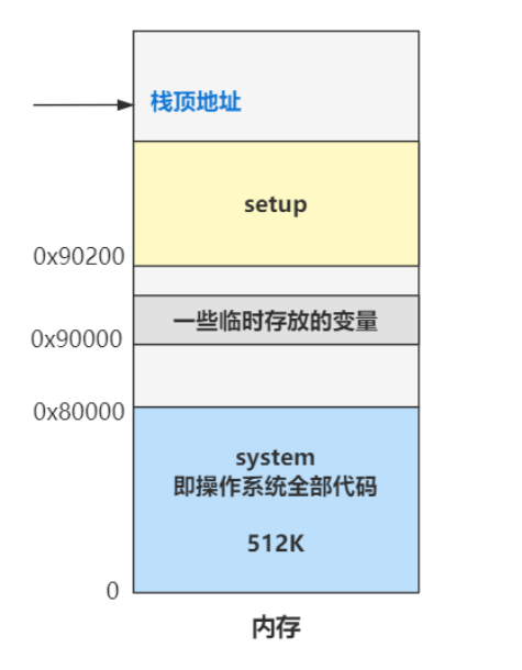
那么现在的内存布局就是这个样子。
end_move:
mov ax,#SETUPSEG ! right, forgot this at first. didn't work :-)
mov ds,ax
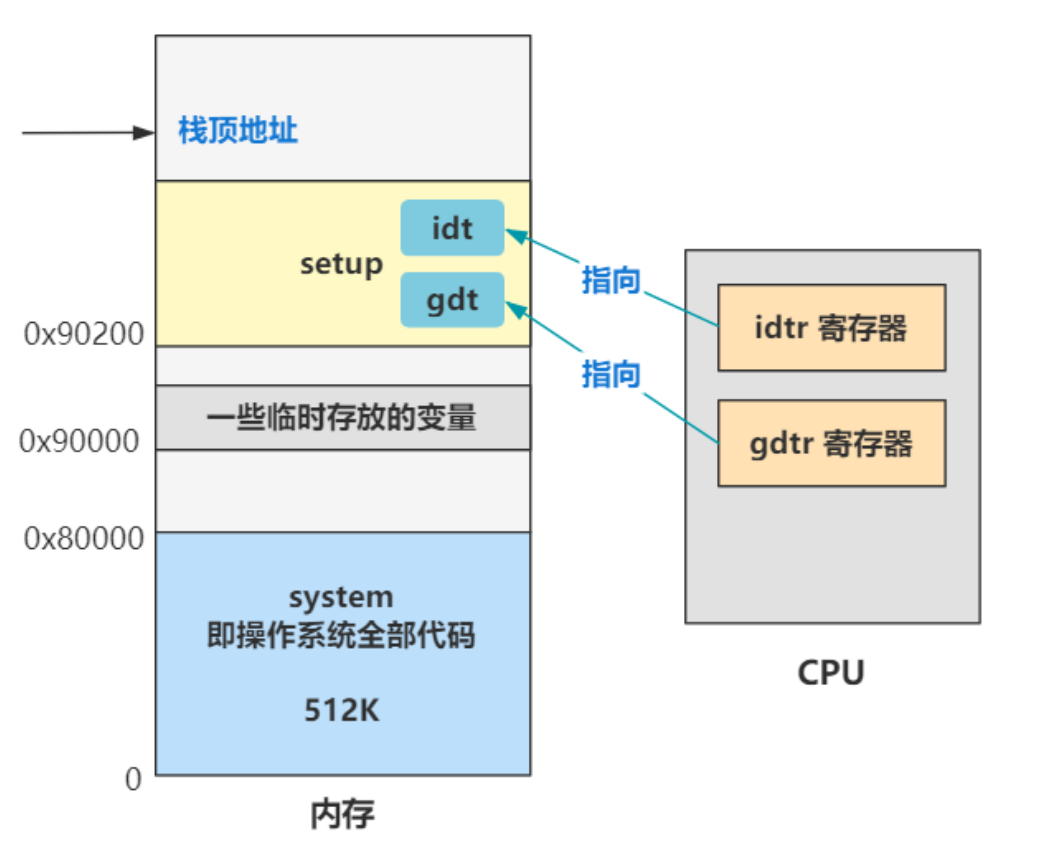
lidt idt_48 ! load idt with 0,0
lgdt gdt_48 ! load gdt with whatever appropriate
...
...
idt_48:
.word 0 ! idt limit=0
.word 0,0 ! idt base=0L
gdt_48:
.word 0x800 ! gdt limit=2048, 256 GDT entries
.word 512+gdt,0x9 ! gdt base = 0X9xxxx
解释:
lidt idt_48 表示把idt_48放在 idtr 寄存器中
idtr寄存器存储的是中断描述符表
lgdt gdt_48 表示把gdt_48放在 gdtr 寄存器中。
其实这段代码是为了开启cpu的保护模式做准备,由于intel的历史遗留问题,cpu的实模式和保护模式的寻址方式不同。实模式是段基址左移4位加偏移地址,即ds<<4+[偏移地址]。保护模式是,在段寄存器(比如 ds、ss、cs)里存储段选择子,段选择子去全局描述符表中寻找段描述符,从中取出段基址,再和偏移地址相加。
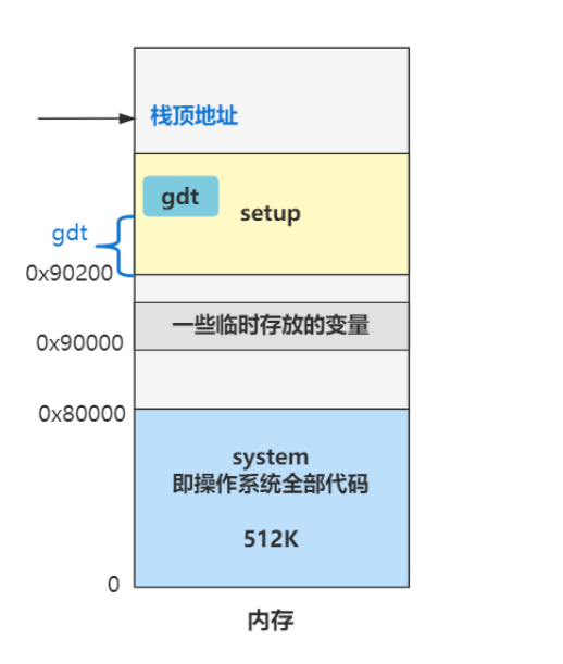
图解:
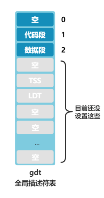
gdt:

	.word	0,0,0,0		! dummy

	.word	0x07FF		! 8Mb - limit=2047 (2048*4096=8Mb)

	.word	0x0000		! base address=0

	.word	0x9A00		! code read/exec

	.word	0x00C0		! granularity=4096, 386

	.word	0x07FF		! 8Mb - limit=2047 (2048*4096=8Mb)

	.word	0x0000		! base address=0

	.word	0x9200		! data read/write

	.word	0x00C0		! granularity=4096, 386
解释:
gdt 这个标签处,就是全局描述符表在内存中的真正数据了。
图解:
	mov	al,#0xD1		! command write

	out	#0x64,al

	mov	al,#0xDF		! A20 on

	out	#0x60,al
解释:
简单理解,这一步就是为了突破地址信号线 20 位的宽度,变成 32 位可用。
! well, that went ok, I hope. Now we have to reprogram the interrupts :-(

! we put them right after the intel-reserved hardware interrupts, at

! int 0x20-0x2F. There they won't mess up anything. Sadly IBM really

! messed this up with the original PC, and they haven't been able to

! rectify it afterwards. Thus the bios puts interrupts at 0x08-0x0f,

! which is used for the internal hardware interrupts as well. We just

! have to reprogram the 8259's, and it isn't fun.

	mov	al,#0x11		! initialization sequence

	out	#0x20,al		! send it to 8259A-1

	.word	0x00eb,0x00eb		! jmp $+2, jmp $+2

	out	#0xA0,al		! and to 8259A-2

	.word	0x00eb,0x00eb

	mov	al,#0x20		! start of hardware int's (0x20)

	out	#0x21,al

	.word	0x00eb,0x00eb

	mov	al,#0x28		! start of hardware int's 2 (0x28)

	out	#0xA1,al

	.word	0x00eb,0x00eb

	mov	al,#0x04		! 8259-1 is master

	out	#0x21,al

	.word	0x00eb,0x00eb

	mov	al,#0x02		! 8259-2 is slave

	out	#0xA1,al

	.word	0x00eb,0x00eb

	mov	al,#0x01		! 8086 mode for both

	out	#0x21,al

	.word	0x00eb,0x00eb

	out	#0xA1,al

	.word	0x00eb,0x00eb

	mov	al,#0xFF		! mask off all interrupts for now

	out	#0x21,al

	.word	0x00eb,0x00eb

	out	#0xA1,al
解释:
看注释,这是对可编程中断控制器 8259 芯片编程,8259是啥就不解释了。
! well, that certainly wasn't fun :-(. Hopefully it works, and we don't

! need no steenking BIOS anyway (except for the initial loading :-).

! The BIOS-routine wants lots of unnecessary data, and it's less

! "interesting" anyway. This is how REAL programmers do it.

!

! Well, now's the time to actually move into protected mode. To make

! things as simple as possible, we do no register set-up or anything,

! we let the gnu-compiled 32-bit programs do that. We just jump to

! absolute address 0x00000, in 32-bit protected mode.

	mov	ax,#0x0001	! protected mode (PE) bit

	lmsw	ax		! This is it!

	jmpi	0,8		! jmp offset 0 of segment 8 (cs)
解释:
前两行,将 cr0 这个寄存器的位 0 置 1,模式就从实模式切换到保护模式了。
再往后,又是一个段间跳转指令 jmpi,后面的 8 表示 cs(代码段寄存器)的值,0 表示偏移地址。请注意,此时已经是保护模式了,之前也说过,保护模式下内存寻址方式变了,段寄存器里的值被当做段选择子。
8 用二进制表示就是
0000,0000,0000,1000
根据段选择子(16位)的结构,描述符索引值是高13位,可以知道描述符索引值是 1,也就是要去全局描述符表(gdt)中找第一项段描述符。
gdt:

	.word	0,0,0,0		! dummy

	.word	0x07FF		! 8Mb - limit=2047 (2048*4096=8Mb)

	.word	0x0000		! base address=0

	.word	0x9A00		! code read/exec

	.word	0x00C0		! granularity=4096, 386

	.word	0x07FF		! 8Mb - limit=2047 (2048*4096=8Mb)

	.word	0x0000		! base address=0

	.word	0x9200		! data read/write

	.word	0x00C0		! granularity=4096, 386
注意,段描述符是64位数,从代码看,就是每8个字节(4个字)为一个段描述符。
这里取的第2个段描述符就是代码段描述符,从代码看就是的5个.word到第8个.word。段基址是 0,偏移也是 0,那加一块就还是 0 咯,所以最终这个跳转指令,就是跳转到内存地址的 0 地址处,开始执行。
目前内存的状态:
system 模块怎么生成的呢?由 Makefile 文件可知,是由 head.s 和 main.c 以及其余各模块的操作系统代码合并来的,可以理解为操作系统的全部核心代码编译后的结果。
我们说,最后一行代码让cpu跳到内存地址的0号处执行,也就是boot/head.s文件所描述的。
上一篇
Linux0.11源码学习(一)
下一篇
Linux0.11源码学习(三)
最新文章
- 运用<div>布局页面练习
- [Python] python vs cplusplus
- 30分钟学会反向Ajax
- Maximum Random Walk(概率dp)
- IO 图
- centos 7 安装mp3解码器
- Log4Net不生成日志文件
- oracle 如何重置用户密码
- QDebug &operator<<出错(根据QString来找,是不得要领的,而是应该根据QString所在的对象来思考)
- Linux的链接文件-ln命令
- params修饰符
- Mysql性能优化之覆盖索引
- html超出显示省略号
- thinkphp5 部署注意事项
- react-router简介
- hive_连续天次计算
- go get Unknown SSL protocol error in connection to gopkg.in
- 发送Http
- 用react编写一个可以编辑的表格
- Python基础之文件的初识函数